Input Devices
Individual assignment:
Measure something: add a sensor to a microcontroller board that you have designed and read it
This week, I decided to go with the MPU6050 sensor module because when I examined the requirements for the final project, I realized that the essential sensor I need is an angle sensor. After some consideration, I concluded that the MPU6050 would be the best option for this purpose.
MPU6050
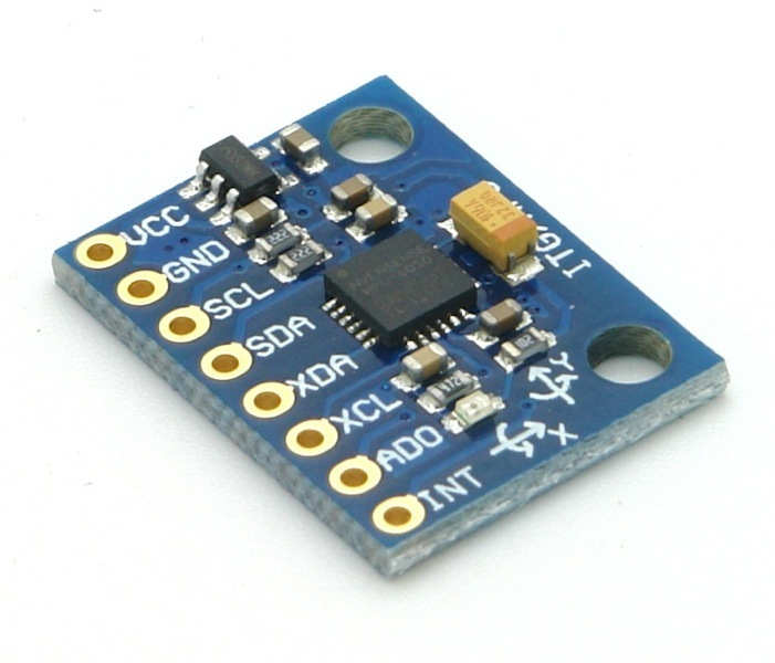
MPU6050 sensor module is complete 6-axis Motion Tracking Device. It combines 3-axis Gyroscope, 3-axis Accelerometer and Digital Motion Processor all in small package. Also, it has additional feature of on-chip Temperature sensor. It has I2C bus interface to communicate with the microcontrollers.
It has Auxiliary I2C bus to communicate with other sensor devices like 3-axis Magnetometer, Pressure sensor etc.
If 3-axis Magnetometer is connected to auxiliary I2C bus, then MPU6050 can provide complete 9-axis Motion Fusion output.
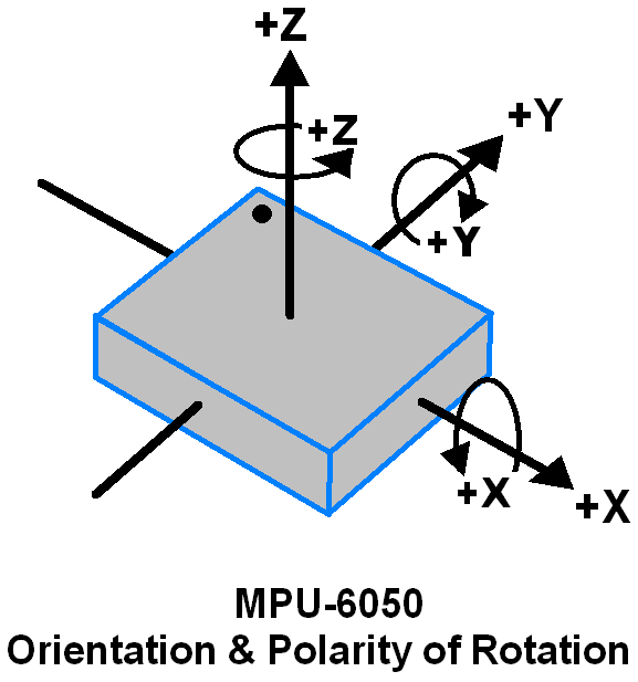
3-Axis Gyroscope
The MPU6050 consist of 3-axis Gyroscope with Micro Electro Mechanical System(MEMS) technology. It is used to detect rotational velocity along the X, Y, Z axes as shown in below figure.
- The MPU6050 detects vibrations caused by the Coriolis Effect when gyros rotate along any of the sensor axes. These vibrations are sensed by an integrated MEM within the MPU6050 module.
- After sensing, the signal undergoes amplification, demodulation, and filtering processes to produce a voltage proportional to the angular rate. This voltage reflects the rate of rotation around the sensed axis.
- Following this, the voltage signal is digitized using a 16-bit Analog-to-Digital Converter (ADC), ensuring precise sampling of each axis.
- The MPU6050 provides various full-scale range options for output, such as +/- 250, +/- 500, +/- 1000, and +/- 2000. These ranges offer flexibility in adjusting the sensor sensitivity as needed.
- In summary, the MPU6050 accurately measures angular velocity along each axis in degrees per second, facilitating reliable motion tracking and analysis across different applications.
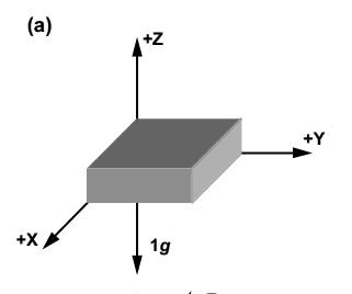
3-Axis Accelerometer
The MPU6050 features a 3-axis accelerometer employing Micro Electro Mechanical (MEMs) technology. This configuration enables the sensor to detect angles of tilt or inclination along the X, Y, and Z axes, as illustrated in the figure below.
- Acceleration along the axes causes displacement of the movable mass.
- This displacement unbalances the differential capacitor, generating sensor output.
- Output amplitude correlates with acceleration and is digitized using a 16-bit ADC.
- The full-scale range of acceleration is configurable, typically set to +/- 2g, +/- 4g, +/- 8g, or +/- 16g.
- Acceleration is measured in g (gravity force) units.
- When the device is placed on a flat surface, it measures 0g on the X and Y axes and +1g on the Z axis.
On-chip Temperature Sensor
On-chip temperature sensor output is digitized using ADC.
The reading from temperature sensor can be read from sensor data register.
MPU6050 Module Pinout
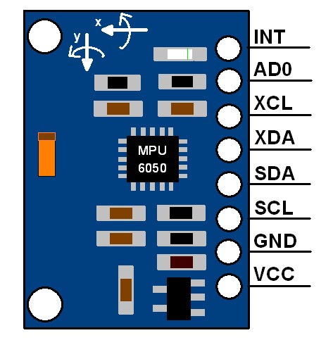
- VCC : This pin is connected to the positive supply voltage (typically 3.3V or 5V).
- GND : This pin is connected to the ground or 0V reference.
- SCL : Serial Clock pin, used for I2C communication.
- SDA : Serial Data pin, used for I2C communication.
- XDA : Auxiliary I2C bus data input/output for connecting external sensors.
- XCL : Auxiliary I2C bus clock input/output for connecting external sensors.
- AD0 : This pin is used for I2C address selection. Its state determines the least significant bit of the I2C address.
- INT : Interrupt output pin, used to indicate data is ready to be read or other events.
Spec of mpu6050
| Sensor Parameter | Gyroscope | Accelerometer | Temperature Sensor | Supply Voltage |
| Sensing Axes | 3-axis | 3-axis | N/A | N/A |
| Full-Scale Range | ±250, ±500, ±1000, ±2000 dps | ±2g, ±4g, ±8g, ±16g | N/A | N/A |
| Sensitivity | 131, 65.5, 32.8, 16.4 LSBs/dps | 16384, 8192, 4096, 2048 LSBs/g | 340 LSBs/°C | N/A |
| Output Data Rate (ODR) | 8kHz to 1.25Hz | 8kHz to 1.25Hz | N/A | N/A |
| Operating Temperature Range | N/A | N/A | -40°C to +85°C | N/A |
| Temperature Sensor Accuracy | N/A | N/A | ±3°C | N/A |
| Supply Voltage Range | N/A | N/A | N/A | 2.375V to 3.46V (MPU-6050), 2.375V to 5.5V (MPU-6050A) |
| Communication Interface | I2C serial interface | I2C serial interface | N/A | N/A |
| Maximum Clock Frequency | 400kHz | 400kHz | N/A | N/A |
| Register Access Modes | 8-bit and 16-bit | 8-bit and 16-bit | N/A | N/A |
| Digital Motion Processor (DMP) | Yes | N/A | N/A | N/A |
| On-Chip ADC Resolution | 16-bit | 16-bit | N/A | N/A |
| Programmable Digital Filters | Yes | Yes | N/A | N/A |
| Interrupts | Yes | Yes | N/A | N/A |
| Low-Power Consumption | 3.9mA (full operation) | N/A | N/A | N/A |
I2C Communication Protocol
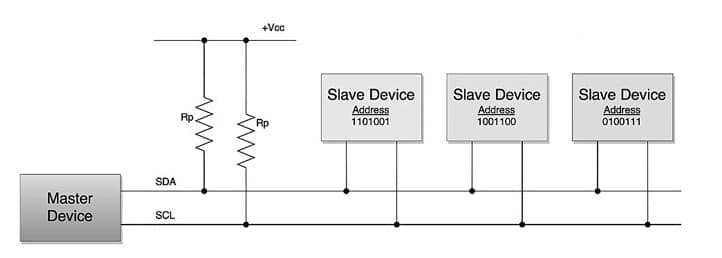
I2C, which stands for Inter-Integrated Circuit, is a bus interface connection protocol that is integrated into devices for serial communication.
It's a commonly used protocol for short-distance communication and is also referred to as Two Wire Interface (TWI).
The I2C communication protocol operates using only 2 bi-directional open-drain lines for data transmission, known as SDA and SCL. Both of these lines are initially pulled high.
- Serial Data (SDA) : Data is transferred through this pin.
- Serial Clock (SCL): This pin carries the clock signal.
I2C operates in 2 modes –
- Master mode
- Slave mode
Every data bit transferred on the SDA line is synchronized by a transition from the high to low pulse of each clock signal on the SCL line.
As per the I2C protocols, the data line cannot change while the clock line is high;
It can only change when the clock line is low.
Since the devices on the I2C bus are actively low, pull-up resistors are required to keep lines high.
Data is transmitted in the form of packets consisting of 9 bits. The sequence of these bits includes:
- Start Condition: 1 bit
- Slave Address: 8 bits
- Acknowledge: 1 bit
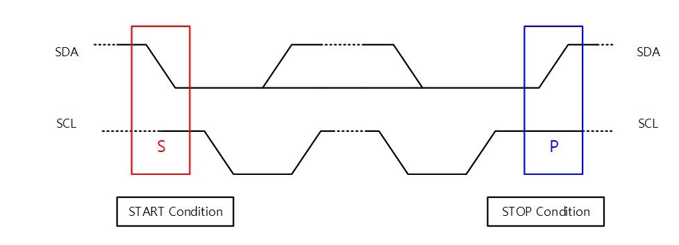
Start and stop conditions
I2C protocols are generated by keeping the SCL line high and changing the level of SDA.
To generate a start condition, the SDA line is transitioned from high to low while keeping SCL high.
Conversely, to generate a stop condition, the SDA line transitions from low to high while keeping the SCL high.
A high Read/Write bit indicates that the master is sending the data to the slave, whereas a low Read/Write bit indicates that the master is receiving data from the slave.
To find the I2C address of the MPU6050 sensor connected
#include <Wire.h>

void setup() {
  Wire.begin();
  Serial.begin(9600);
  while (!Serial); // Wait for the serial connection to be established
  Serial.println("\nI2C Scanner");
}

void loop() {
  byte error, address;
  int nDevices;

  Serial.println("Scanning...");

  nDevices = 0;
  for (address = 1; address < 127; address++) {
    // The I2C scanner uses the return value of
    // the Wire.endTransmission to see if
    // a device did acknowledge to the address.
    Wire.beginTransmission(address);
    error = Wire.endTransmission();

    if (error == 0) {
      Serial.print("I2C device found at address 0x");
      if (address < 16)
        Serial.print("0");
      Serial.print(address, HEX);
      Serial.println("  !");

      nDevices++;
    } else if (error == 4) {
      Serial.print("Unknown error at address 0x");
      if (address < 16)
        Serial.print("0");
      Serial.println(address, HEX);
    }
  }
  if (nDevices == 0)
    Serial.println("No I2C devices found\n");
  else
    Serial.println("done\n");

  delay(5000); // wait 5 seconds for the next scan
}
This program scans all possible I2C addresses and reports any devices it finds
The Serial Monitor will display the I2C addresses of any connected devices. The MPU6050 typically has an I2C address of
0x68
or
0x69
This confirms that the MPU6050 is connected and its I2C address is 0x68 .
If you have any issues or don't see any devices, double-check your connections and ensure that the MPU6050 is properly powered.
From this point, I started working with the ATtiny chipboard that I had created during the output devices week .
Afterward, I began programming the ATtiny board. However,
I soon realized that the ATtiny board couldn't run the required library. Consequently, I shifted my focus to prompting the GPT for code compatible with the ATtiny and MPU6050, aiming to obtain gyroscopic data.
here is the code that i have used
#include <Wire.h>

#define MPU_ADDR 0x68 // MPU-6050 I2C address

// MPU-6050 register addresses
#define REG_ACCEL_XOUT_H 0x3B
#define REG_GYRO_XOUT_H 0x43
#define REG_PWR_MGMT_1 0x6B

void setup() {
  Wire.begin(); // Initialize I2C communication
  Serial.begin(9600); // Initialize serial communication

  // Wake up MPU-6050
  Wire.beginTransmission(MPU_ADDR);
  Wire.write(REG_PWR_MGMT_1);
  Wire.write(0); // Clear sleep mode bit
  Wire.endTransmission(true);
}

void loop() {
  // Read accelerometer data
  int16_t accel_x, accel_y, accel_z;
  readSensor(REG_ACCEL_XOUT_H, &accel_x, &accel_y, &accel_z);

  // Read gyroscope data
  int16_t gyro_x, gyro_y, gyro_z;
  readSensor(REG_GYRO_XOUT_H, &gyro_x, &gyro_y, &gyro_z);

  // Print values
  Serial.print("Acceleration X: ");
  Serial.print(a.acceleration.x);
  Serial.print(", Y: ");
  Serial.print(a.acceleration.y);
  Serial.print(", Z: ");
  Serial.print(a.acceleration.z);
  Serial.println(" m/s^2");
  Serial.print("Rotation X: ");
  Serial.print(g.gyro.x);
  Serial.print(", Y: ");
  Serial.print(g.gyro.y);
  Serial.print(", Z: ");
  Serial.print(g.gyro.z);
  Serial.println(" rad/s");
  Serial.print("Temperature: ");
  Serial.print(temp.temperature);
  Serial.println(" degC");
  Serial.println("");
  delay(1000);
}

void readSensor(uint8_t reg_addr, int16_t* x, int16_t* y, int16_t* z) {
  Wire.beginTransmission(MPU_ADDR);
  Wire.write(reg_addr);
  Wire.endTransmission(false);
  Wire.requestFrom(MPU_ADDR, 6, true);

  *x = (Wire.read() << 8) | Wire.read();
  *y = (Wire.read() << 8) | Wire.read();
  *z = (Wire.read() << 8) | Wire.read();
}
Initially, I faced issues getting accurate values from the gyroscope. After utilizing the interrupt pin, the values became more precise.
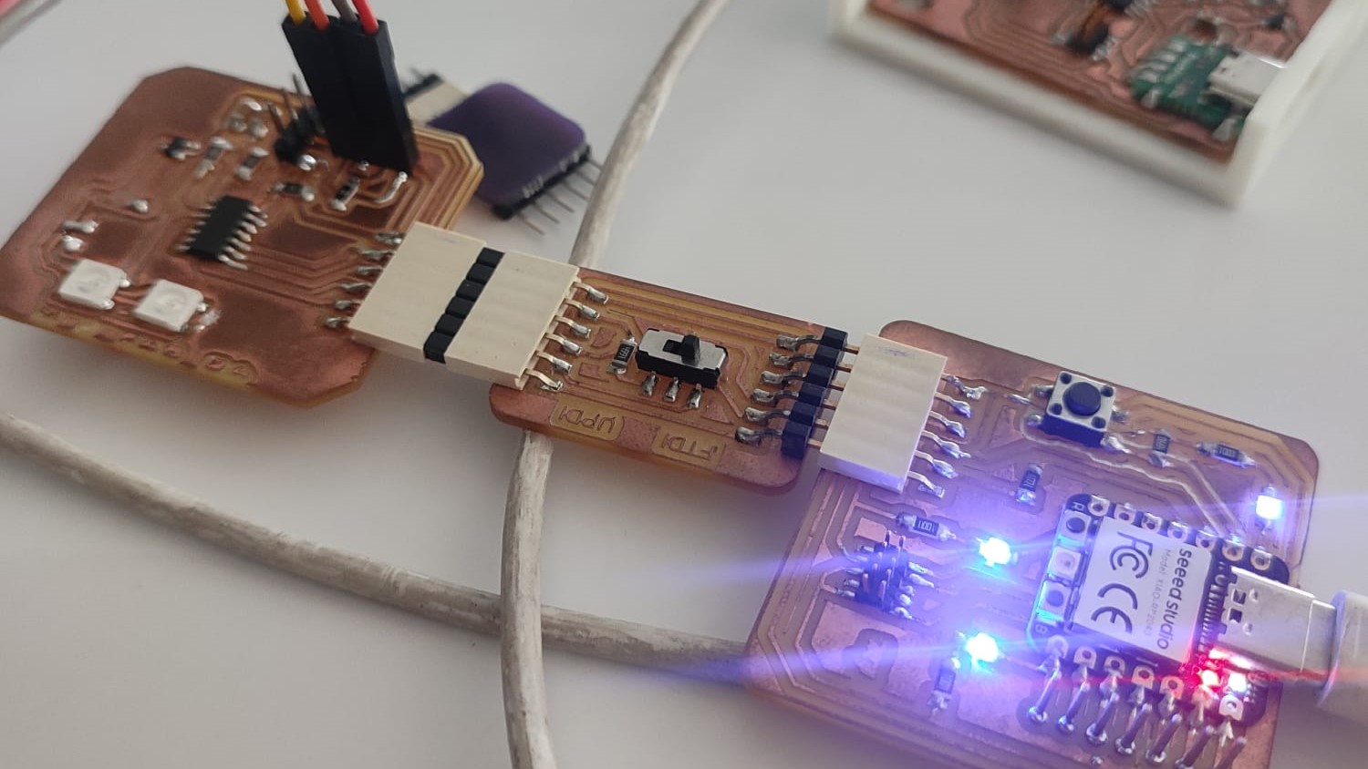
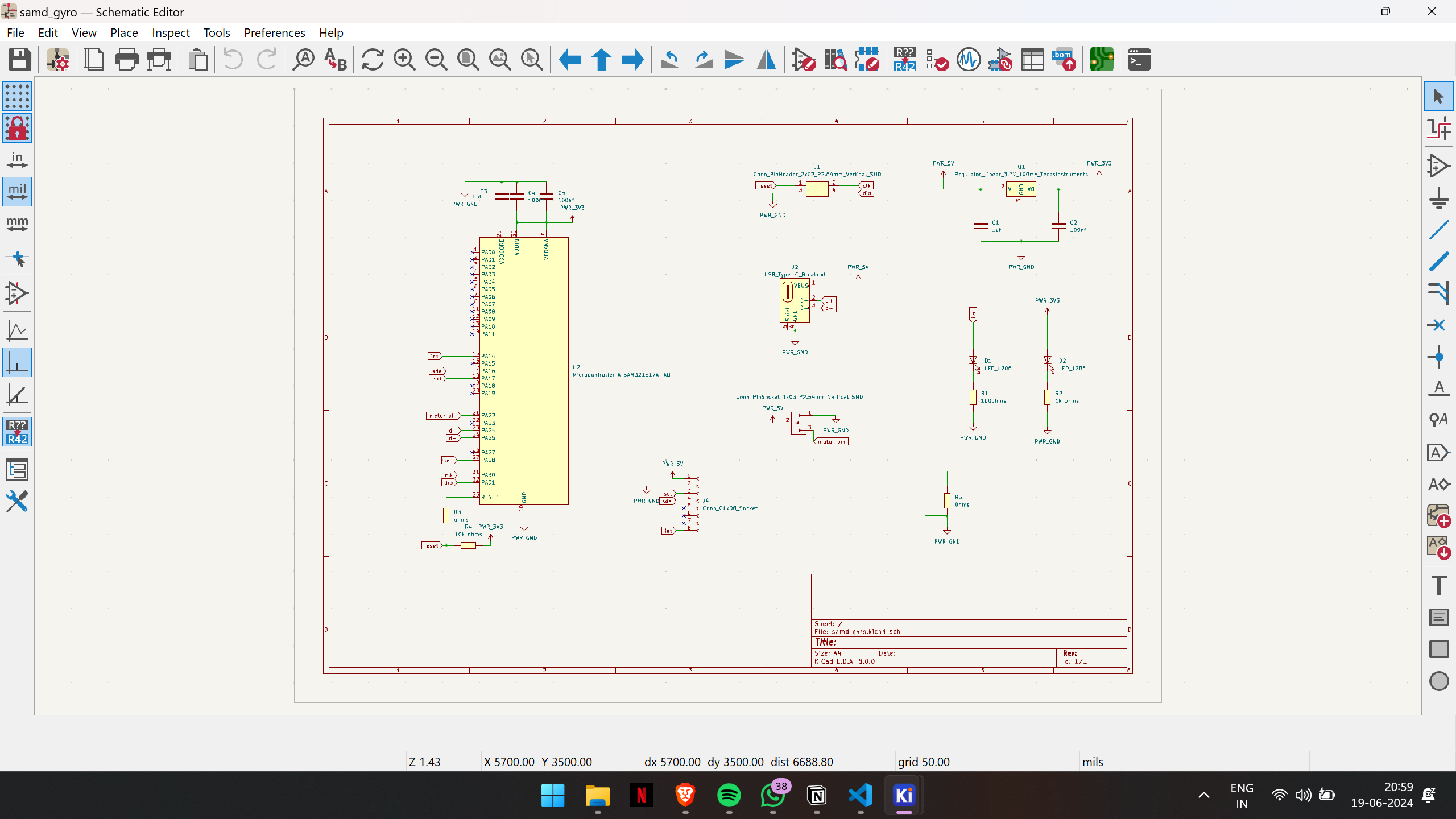
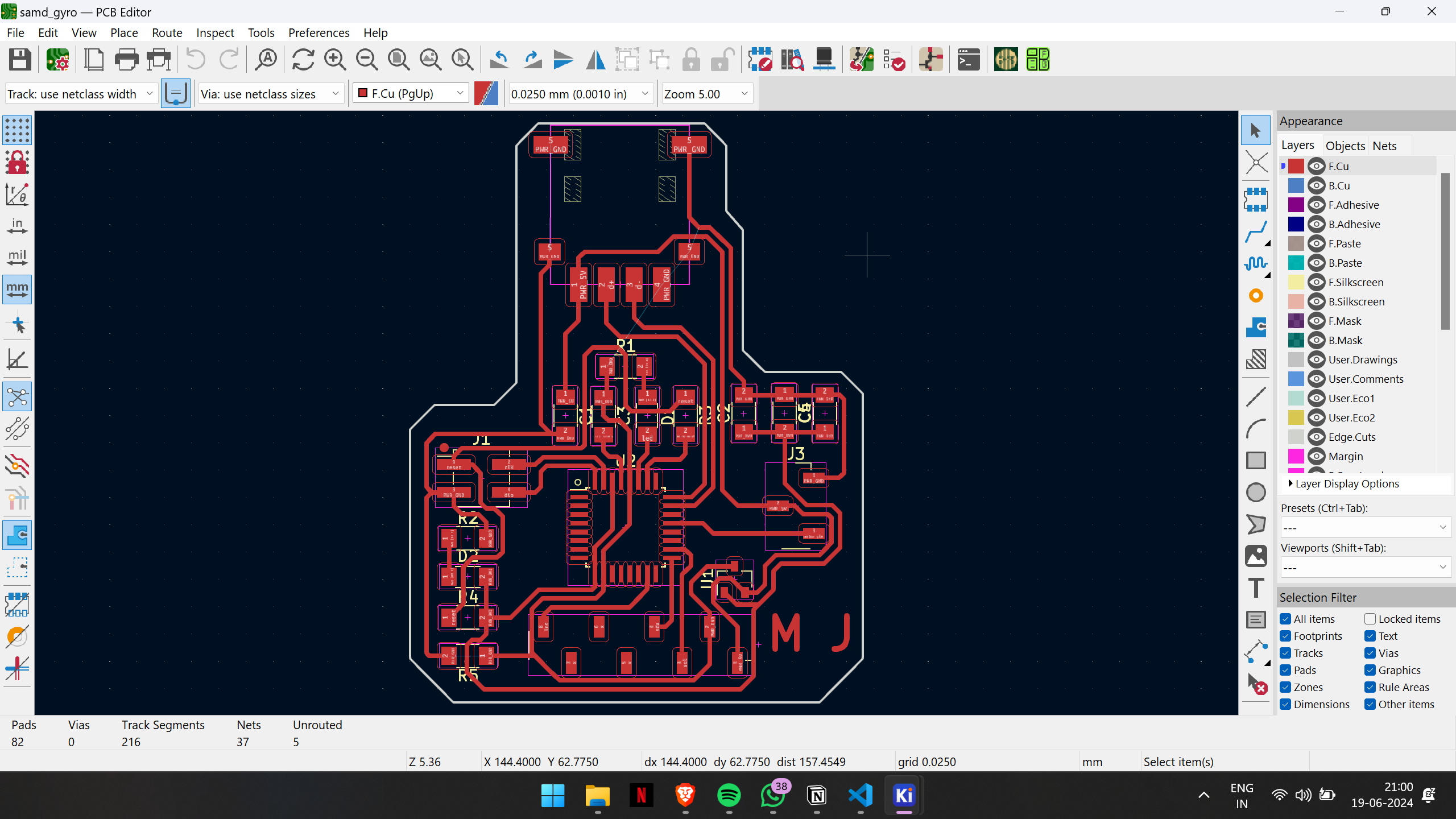
I had to mill another board because the board from the Output week didn't have an interrupt pin. So, I designed and milled a new board, this time using the SAMD21 IC, as it has enough space for the necessary libraries also.
This is the output in the new board that i have created
When considering the final project, I realized that adding a servo to the setup would complete the electronics portion.
Therefore, I decided to test the code I had initially written. I began by using the Arduino Uno that I had on hand. I connected both the MPU6050 and the servo motor to it, and then attempted to program them together.
Since I'm not particularly skilled at programming, I sought the assistance of ChatGPT to help me with the coding process. After continuously prompting ChatGPT for suggestions, I eventually pieced together something that seemed like it would work for the project.
#include "I2Cdev.h"
#include "MPU6050_6Axis_MotionApps20.h"

#if I2CDEV_IMPLEMENTATION == I2CDEV_ARDUINO_WIRE
#include "Wire.h"
#endif
#include <Servo.h>

MPU6050 mpu;
Servo servo;
Quaternion q;           // quaternion container
VectorFloat gravity;    // gravity vector

#define INTERRUPT_PIN 2  // use pin 2 on Arduino Uno & most boards

bool dmpReady = false;  // set true if DMP init was successful
uint8_t mpuIntStatus;   // holds actual interrupt status byte from MPU
uint8_t devStatus;      // return status after each device operation (0 = success, !0 = error)
uint16_t packetSize;    // expected DMP packet size (default is 42 bytes)
uint16_t fifoCount;     // count of all bytes currently in FIFO
uint8_t fifoBuffer[64]; // FIFO storage buffer
volatile bool mpuInterrupt = false;

float initialYaw = 0.0; // initial yaw value for calibration
bool calibrated = false; // flag to indicate if calibration is done

void setup() {
  Wire.begin();
  Serial.begin(38400);
  while (!Serial);

  mpu.initialize();
  pinMode(INTERRUPT_PIN, INPUT);
  devStatus = mpu.dmpInitialize();
  mpu.setXGyroOffset(17);
  mpu.setYGyroOffset(-69);
  mpu.setZGyroOffset(27);
  mpu.setZAccelOffset(1551);

  if (devStatus == 0) {
    mpu.setDMPEnabled(true);
    attachInterrupt(digitalPinToInterrupt(INTERRUPT_PIN), dmpDataReady, RISING);
    mpuIntStatus = mpu.getIntStatus();
    dmpReady = true;
    packetSize = mpu.dmpGetFIFOPacketSize();
  }

  servo.attach(9); // Change to the pin your servo is connected to
}

void loop() {
  if (!dmpReady) return;

  while (!mpuInterrupt && fifoCount < packetSize) {
    if (mpuInterrupt && fifoCount < packetSize) {
      fifoCount = mpu.getFIFOCount();
    }
  }

  mpuInterrupt = false;
  mpuIntStatus = mpu.getIntStatus();
  fifoCount = mpu.getFIFOCount();

  if ((mpuIntStatus & _BV(MPU6050_INTERRUPT_FIFO_OFLOW_BIT)) || fifoCount >= 1024) {
    mpu.resetFIFO();
    fifoCount = mpu.getFIFOCount();
    Serial.println(F("FIFO overflow!"));
  } else if (mpuIntStatus & _BV(MPU6050_INTERRUPT_DMP_INT_BIT)) {
    while (fifoCount < packetSize) fifoCount = mpu.getFIFOCount();
    mpu.getFIFOBytes(fifoBuffer, packetSize);
    fifoCount -= packetSize;

    float ypr[3];
mpu.dmpGetQuaternion(&q, fifoBuffer);
mpu.dmpGetGravity(&gravity, &q);
mpu.dmpGetYawPitchRoll(ypr, &q, &gravity);
ypr[0] = ypr[0] * 180 / M_PI;

Serial.print("Yaw angle: ");
Serial.println(ypr[0]); // Print the yaw angle to the serial monitor

if (!calibrated) {
  initialYaw = ypr[0]; // Store initial yaw value for calibration
  calibrated = true;
} else {
  // Check if the yaw value has changed significantly from initial
  if (abs(ypr[0] - initialYaw) > 5) { // You can adjust the threshold angle here
    // Turn servo to 60 degrees
    servo.write(10);
  } else {
    // Return servo to initial position
    servo.write(90); // Adjust this value according to your servo's initial position
  }
}

  }
}

void dmpDataReady() {
  mpuInterrupt = true;
}
I started by sourcing an example code for the MPU6050 and then combined it with the code for the servo motor. Afterward, I reviewed the code and removed any unnecessary parts to streamline it for my project.
Group assignment: click here
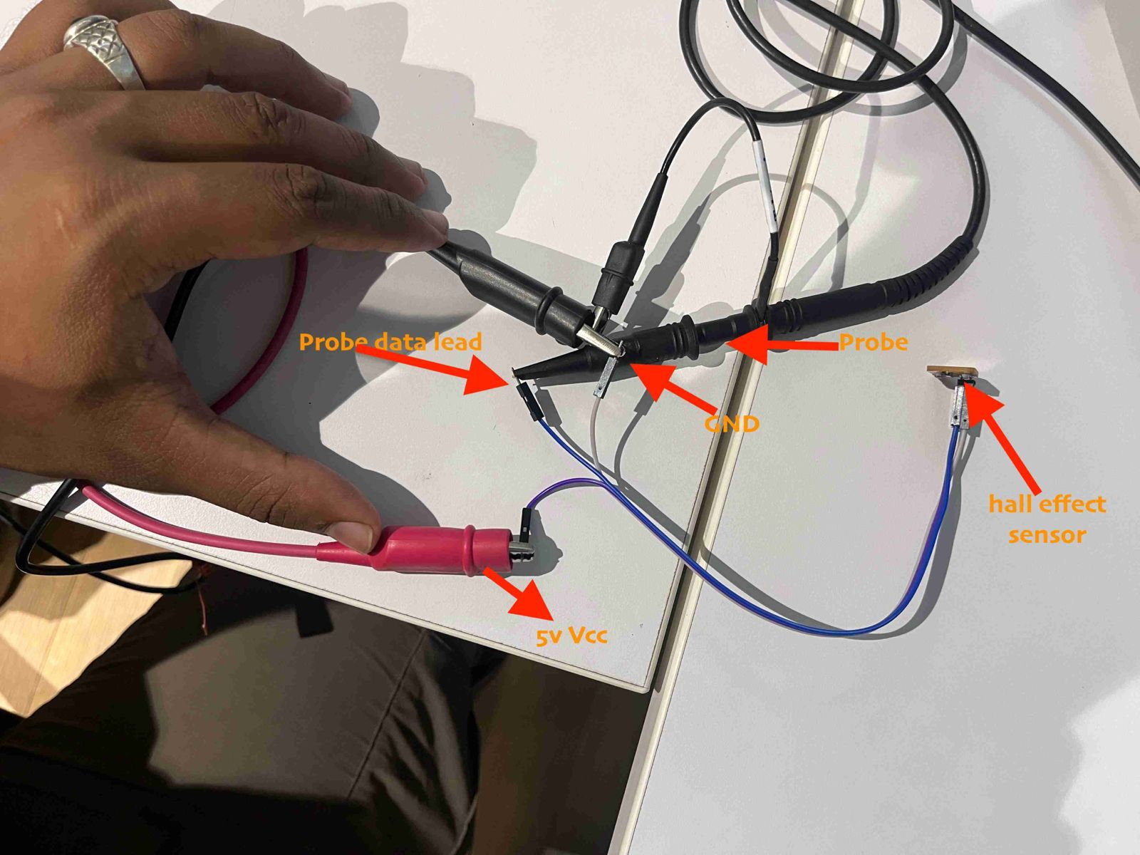
Probe an input device's analog levels and digital signals